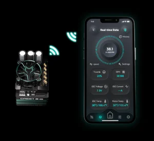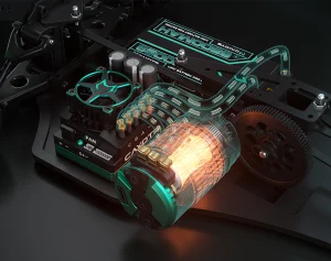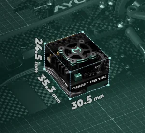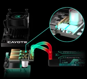


The RC car electronic speed controller is a core component that determines the vehicle’s performance, handling, and reliability. Incorrect installation can not only lead to poor performance but may even permanently damage your RC car and other equipment.
What Preparations are Needed to Install an RC Car Electronic Speed Controller?
Before starting the installation, careful planning and correct equipment selection are key to success.
Selecting the Right ESC for RC Car
First, you need to choose a suitable ESC that matches your motor, battery, and application scenario. If you have questions about choosing an ESC, you can refer to this article, “How to Choose the Right ESC for Your RC Car?“, which provides a detailed explanation.
Tools Preparation
Soldering Iron: Use a soldering iron with a wattage of at least 60W for soldering the battery connector and motor wires.
Solder Wire: Solder wire with flux is used for connecting wires and electronic components.
Solder Paste/Soldering Agent: Used to clean the soldering iron tip and assist in soldering, ensuring bright and strong solder joints.
Hex Wrench/Screwdriver: Used to remove chassis brackets, receiver, or motor mounting screws.
Heat Gun: Used to shrink heat-shrink tubing; more professional and safer than a lighter.
Supplementary Materials
Heat Shrink Tubing in Various Colors: Used for insulation and protection of solder joints.
High-Quality Double-Sided Foam Tape: Used to secure the ESC, receiver, etc., to the chassis; automotive or industrial-grade strong tape should be selected.
Nylon Cable Ties: Used for bundling and organizing wire harnesses.
Braided Cable Management: Used for aesthetics and protection of wire harnesses.
Thermal Conductive Silicone/Pads: Required if you plan to use a metal chassis for heat dissipation.
Screw Adhesive: A medium-strength screw adhesive used to secure motor screws and prevent them from loosening due to vibration.
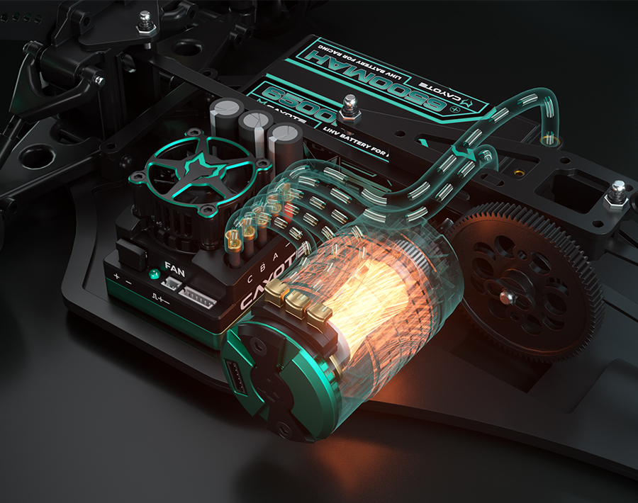
Principles to Follow When Installing an RC Car Electronic Speed Controller
Safety: All wiring operations must be performed with the battery completely disconnected. Ensure the positive and negative terminals are never short-circuited.
Stable: Electronic equipment such as the ESC and receiver must be securely fixed to the frame and must not shift or fall off during severe vibrations.
Heat Dissipation: The electronic speed controller is one of the main heat sources and must be installed in a well-ventilated location or a place that can effectively conduct heat.
Neatness: The wiring harness layout should be clear and reasonable, avoiding interference with transmission components (driveshaft, belt, gears) and facilitating future maintenance.
RC Car Electronic Speed Controller Installation Step-by-Step Guide
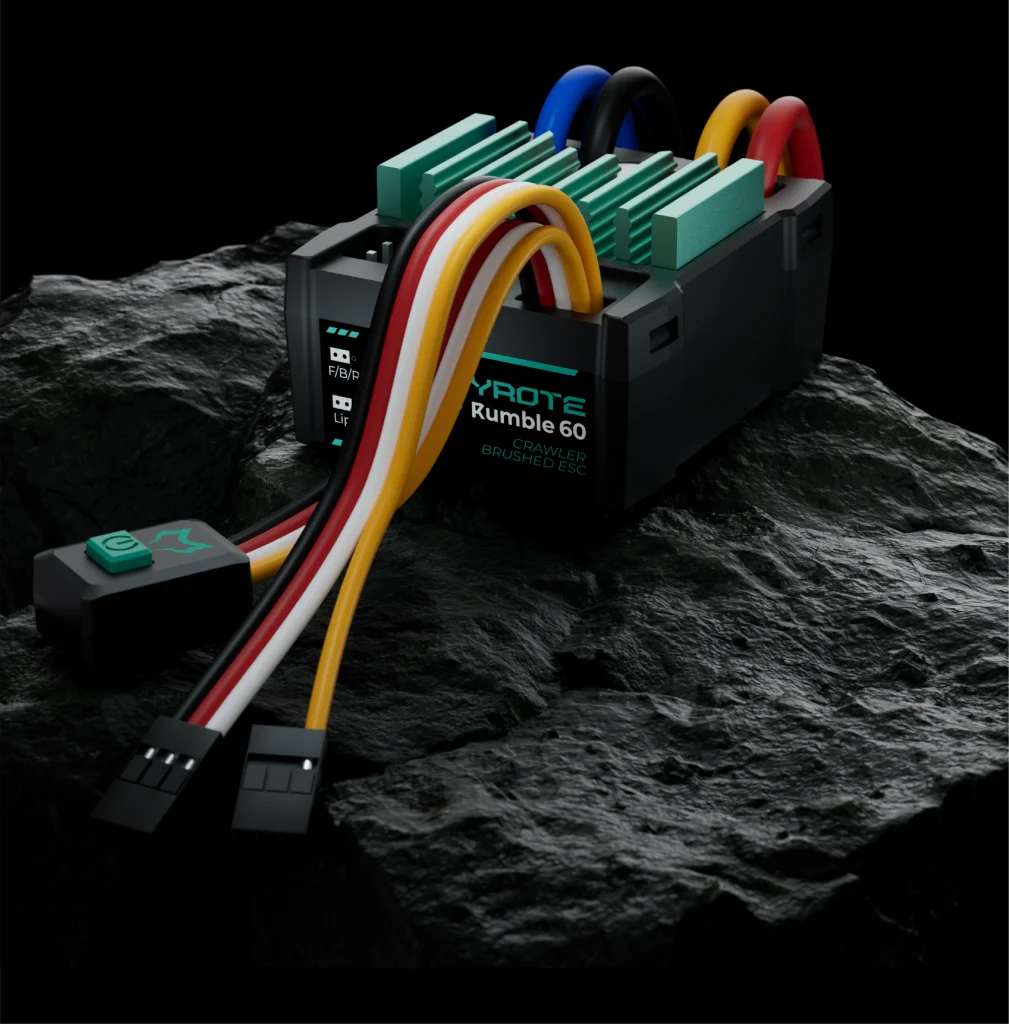
In the following, we will use the CAYOTE RC car racing ESC as an example to explain the installation steps in detail.
Step 1: Planning the Layout and Determining the ESC Position
Weight Distribution
Before installing the rc car electronic speed controller, test-place all electronic equipment, including the ESC, receiver, battery, and servo motors, on the chassis. Prioritize placing heavier components (battery, motor, ESC) near the chassis centerline and in a lower position to achieve optimal balance.
Wiring Planning
The ESC should be placed in a location with good air circulation and heat dissipation. Secondly, ensure that all wiring harnesses connect to the target via the shortest and most direct path, avoiding excessively long cables tangled together.
Step 2: Connecting the ESC to the Motor
For CAYOTE sensored brushless ESCs, the A/B/C terminals of the ESC must be connected one-to-one with the A/B/C markings on the motor to ensure the ESC can correctly interpret the Hall sensor signal. Connect the sensor wires to the corresponding sensor ports. If problems such as jitter or lack of power occur after connection, first check terminals A, B, and C. Is there a problem with the wiring corresponding to C
For our sensorless brushless ESC, the three ESC wires can usually be connected in any order during installation. If the motor rotates in the wrong direction, swap any two of the three motor wires, and the motor will rotate in the correct direction.
For brushed motors: Connect the positive (+) and negative (−) motor wires of the ESC to the corresponding polarity terminals of the motor.
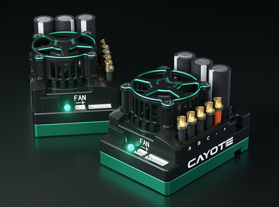
Step 3: Connect the Receiver and Battery
Connect the ESC’s throttle signal wire to the throttle channel of the receiver.
Connect the battery: please confirm that your battery voltage/cell count matches the specifications supported by the connected ESC. Before insertion, ensure the battery and ESC connectors are polarity matched, connecting the positive and negative terminals one by one.
Step 4: Wiring Harness Organization
Securing Cables: After all wiring is connected, use cable ties to bundle all wiring harnesses in the same direction. Secure all harnesses to the chassis using cable ties or double-sided tape, ensuring they are kept away from any rotating parts (such as drive shafts, tires, gears) and high-temperature components (such as motor housings).
Reducing Friction: For harnesses that may rub against the edges of the chassis or carbon fiber plate, wrap them with braided tubing or apply abrasion-resistant tape to contact points to reduce wear.
Proper installation and standardized wiring are the first step in ensuring the ultimate performance and long lifespan of your RC car. By following the above steps and safety principles, you can easily complete the installation and upgrade of the ESC. If you have any questions during the installation process or with CAYOTE ESC programming, please feel free to contact us.